Goals
By the end of this workshop, participants will know how to:
- Order, set up, and test WiReSens zero potential readout circuits
- Analyze tactile sensing data
- Order and assemble flex PCB tactile sensors
Prerequisites
- Step 1: Download the driver according to your OS
- Step 2: Unzip the folder and find the silabser.inf file
- Step 3: Right click the silabser.inf file and select "Install"
Resistive Tactile Sensing Speedrun
Resistive tactile sensors are particularly useful for capturing spatially distributed, dynamic forces. A resistive tactile sensing system built with WiReSens will have three high-level components: the sensor, a readout circuit, and a microcontroller.
Let's have a closer look at each.
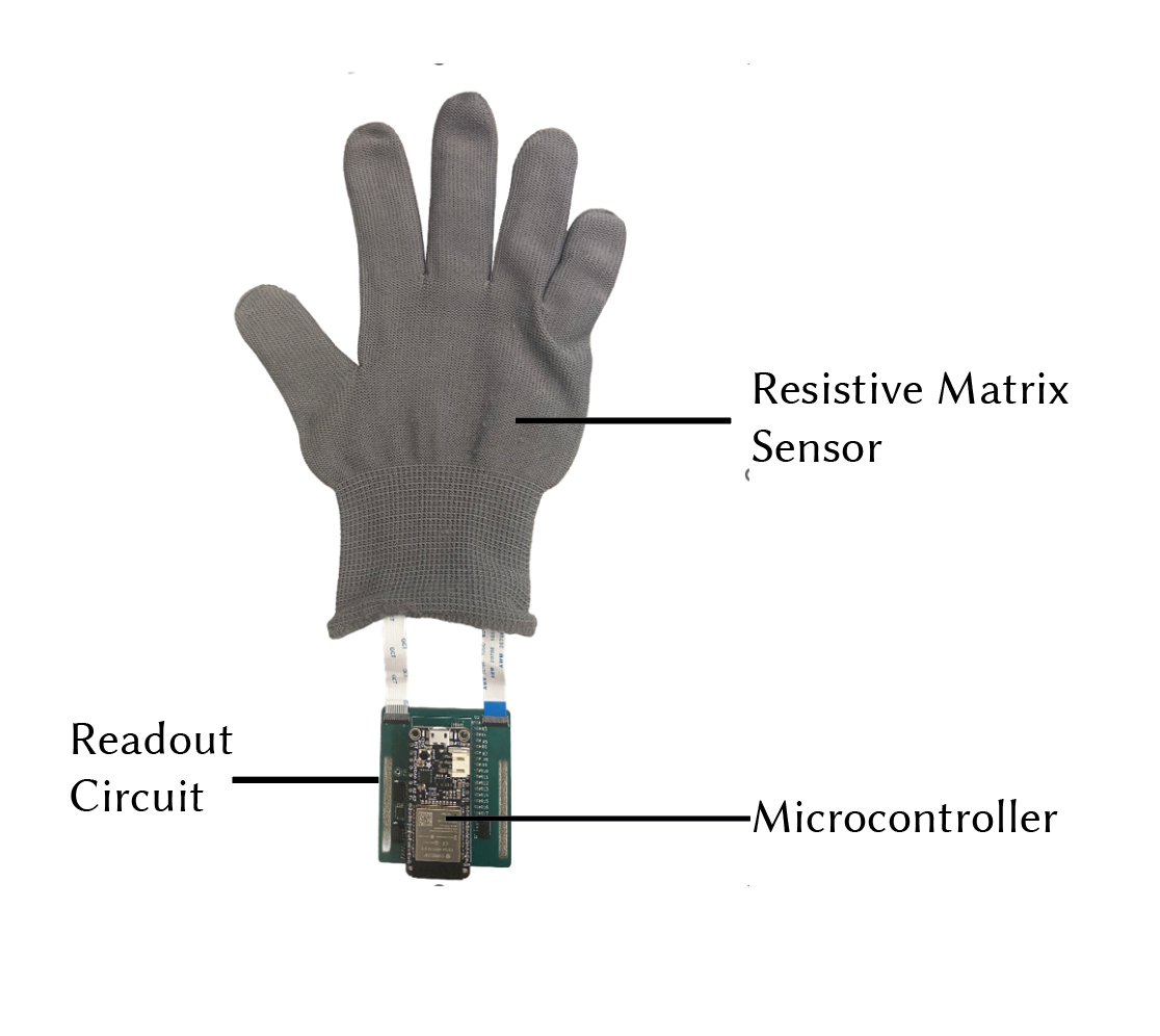
Resistive Matrix Tactile Sensors
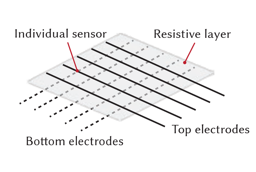
Resistive matrix-based sensors are made by orthogonally arranging top and bottom electrodes over a piezoresistive layer. They measure pressure through the change in resistance at the intersections of these electrodes.
- WiReSens supports up to 16×16 sensors
Readout Circuit
To actually measure this change in resistance, a voltage divider circuit is traditionally used.
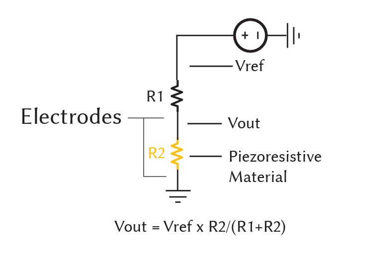
While simple and minimal, you'll encounter two major problems if you stop here.
The first is you'll get a lot of "cross-talk". In other words, if you apply pressure at one individual sensing "node", all of the surrounding nodes will see a change in resistance also. This is because the current has lots of paths it can travel.
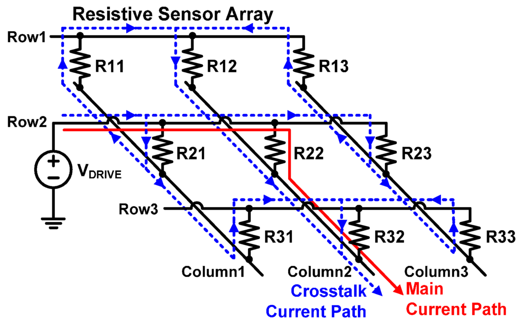
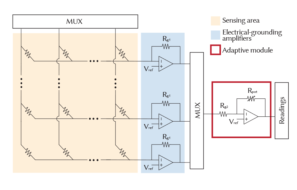
You can solve this by adding an "op amp" on the read-in side of the sensing array — our circuit does exactly this.
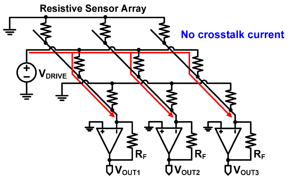
The second problem is the sensitivity and range of pressures we can sense is limited by the choice of R1. If our piezoresistive material has a high base resistance (R2) relative to R1, Vout will always read ~Vref. Similarly if R2 is low relative to R1, Vout will always read ~0V.
Adding a digital potentiometer allows us to control this R1 value, and effectively tune the "sensitivity"/range of the system for different sensors.
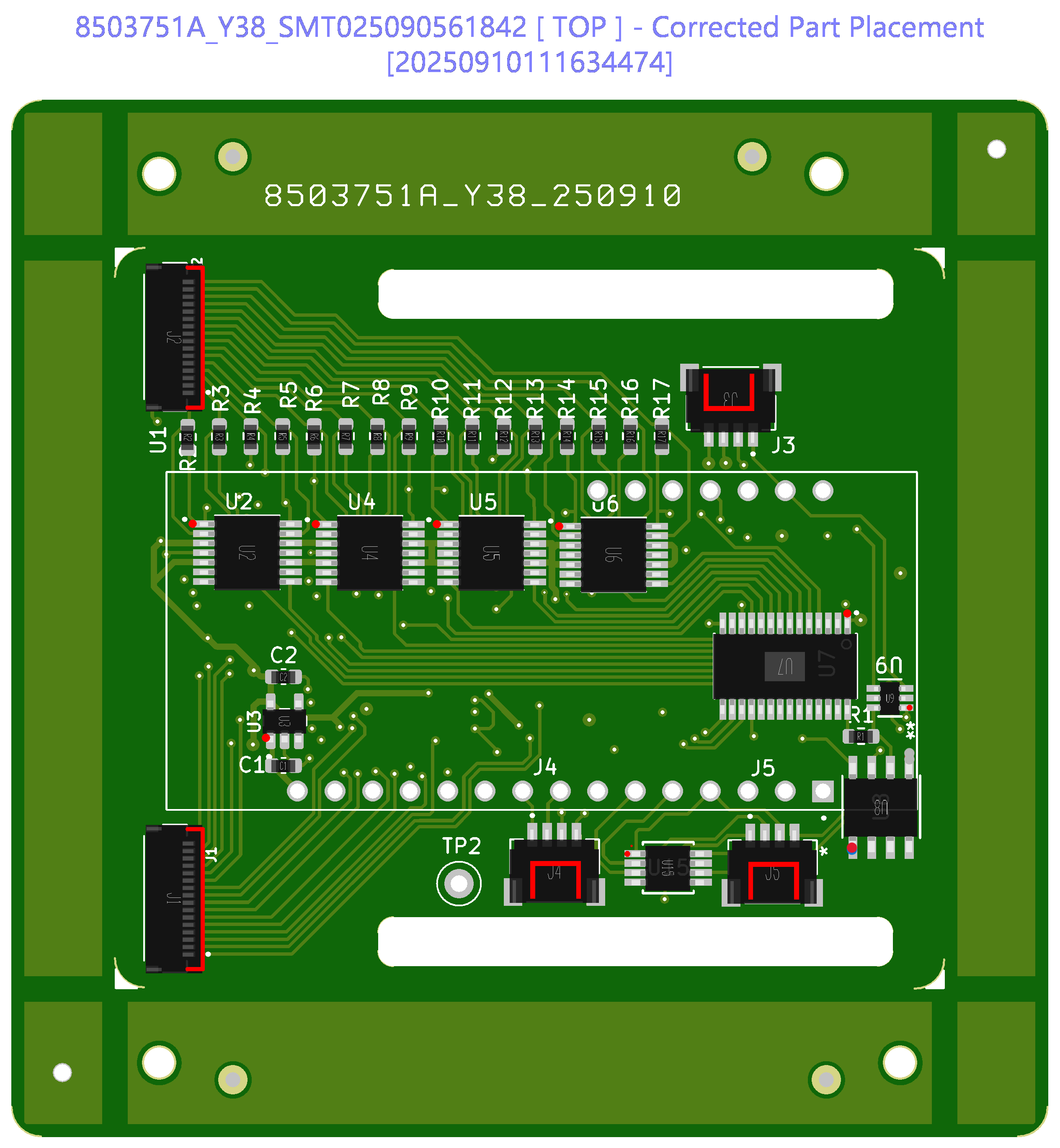
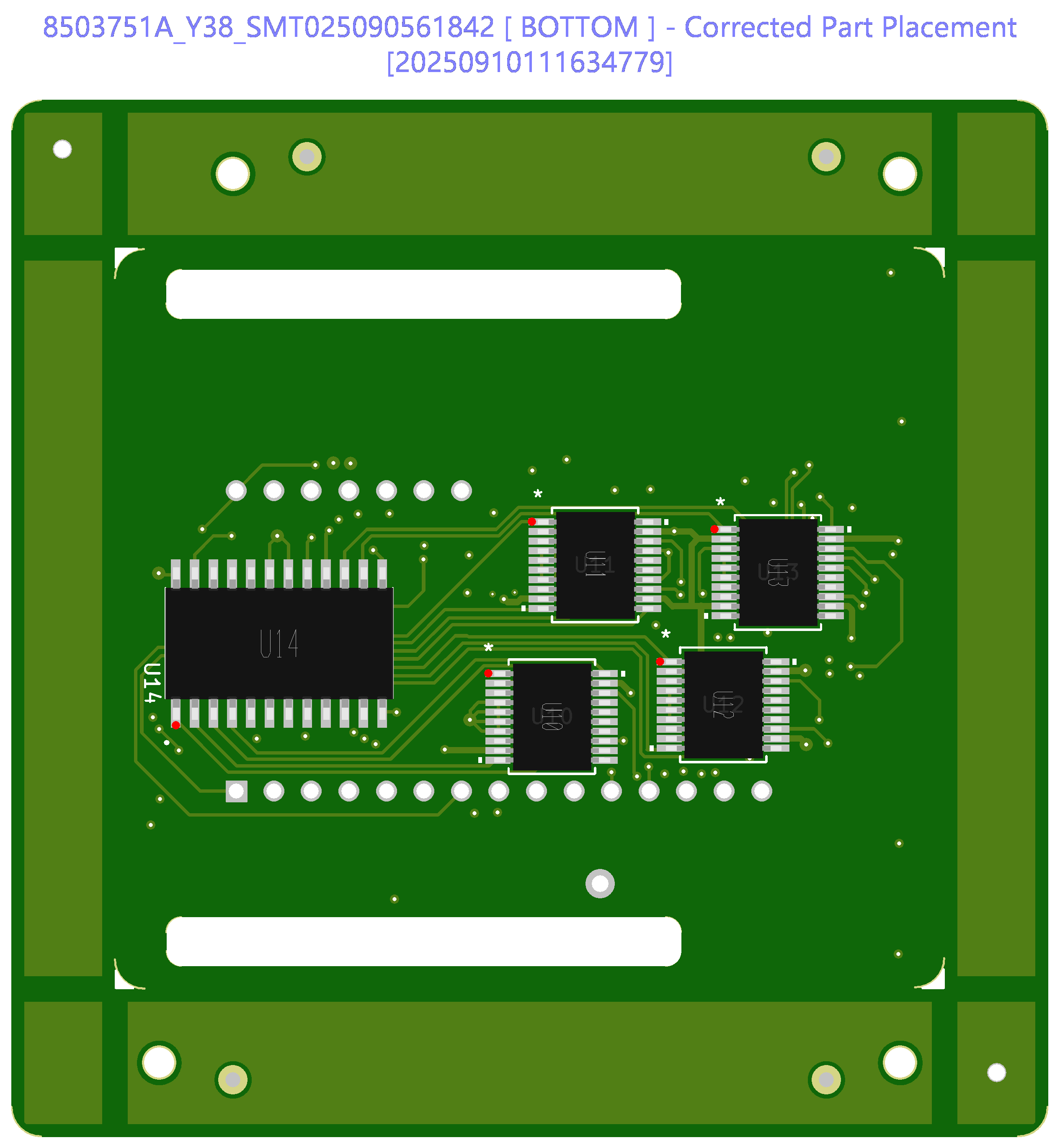
- Uses flex cable connectors to interface with the tactile sensor
- Qwiic ports available for interfacing with other sensors via I2C or ESP analog read
- Works best if the base resistance of your sensor is between 300 Ω and 50 kΩ
- Uses external ADC for improved sampling rate
Microcontroller
The microcontroller's main job is to 1) scan the sensing array, 2) read the sensor values, and 3) transmit the sensor values to your laptop.
We use the Adafruit Feather ESP32, mainly because it's familiar, has native LiPo battery ports/charging, works wirelessly, and has compact access to lots of I/O.
- We support and recommend wireless communication via the ESP-NOW protocol — more information in the firmware sections
The Readout Circuit
This section covers ordering, programming, and verifying the readout circuit before connecting sensors.
Ordering the PCB
The PCB is best ordered through JLCPCB. Detailed step by step instructions are provided at this site: PCB Docs.
- Download the PCB design files (gerbers + BOM) from the above link
- Upload gerber files to JLCPCB
- Select appropriate board specifications
- Upload BOM and component placement for assembly
- Order the Adafruit Feather ESP32 V2 — one per PCB for USB connection, or two for wireless
- Order (female) headers for the microcontroller and (male) headers for the breakout board — headers
- Order flex cable connectors (16 pins, 0.5mm pitch, any length and type)
- Order an FFC breakout board (16 pins, 0.5mm pitch)
- (Optional) Order ribbon cables
- (Optional) Order LiPo batteries from Adafruit — other brands may have reversed polarity, which can damage the microcontroller
Downloading Firmware to the PCB
Firmware is flashed directly from your browser using WiReSens-Online — no local toolchain required.
- Solder the header pins to the PCB and plug in the ESP32. The USB port should face the FFC connectors; the back pins of the ESP32 align with the back pins of the readout circuit (pins will hang out at the front — that is normal).
- Connect the transmitter microcontroller to your laptop via USB.
- Open wiresens-online.vercel.app in Chrome.
- In the Connection panel, click Transmitter → Flash firmware.
- If you are using wireless transmission, repeat the process for the receiver: connect it via USB and click Receiver → Flash firmware.
- For the receiver, also click the Pair button to pair it to the transmitter.
Testing the PCB
After flashing, verify everything is functioning from WiReSens-Online before attaching sensors.
- With the transmitter connected via USB, click the Connect button in WiReSens-Online. Confirm you can see the packet counter increasing — this means the device is communicating correctly.
- If using a receiver, click Connect on the receiver as well and confirm its packet counter is also increasing.
- While the transmitter is connected, you can adjust the gain of the sensor to tune sensitivity for your specific sensor material.
- You can also switch between wireless and wired transmission modes from this panel.
Record and Analyze Data
Once the readout circuit is connected and transmitting, this section covers how to capture, process, and visualize tactile sensing data.
WiReSens-Online
WiReSens-Online is a browser-based tool for connecting WiReSens devices, flashing firmware, configuring settings, and visualizing and recording tactile sensing data — no local software installation required.
- Flash firmware to the transmitter and receiver directly from the browser
- Pair the receiver to the transmitter with a single click
- Monitor live packet counts to confirm the device is communicating
- Adjust the sensor gain while connected to tune sensitivity
- Switch between wireless and wired transmission modes
- Record data sessions using the Record button
WireSensBackend
WireSensBackend is a Python library for recording data locally and performing offline analysis. Use it when you need more control over the recording process, want to interface with other technologies, or are building a custom application. The backend also supports multiple devices simultaneously. The repository includes a GitHub Codespace so you can start using it immediately without any local setup.
Flex PCB Sensors
The sensing element is a flexible PCB that conforms to a glove substrate. This section covers ordering and assembling pre-made flex PCB glove sensors, and designing custom sensor layouts for your own application.
Ordering & Assembling Gloves
Detailed documentation for ordering and assembling the flex PCB glove sensors already exists — follow the guide below, which covers everything from sourcing components to final assembly.
Flex PCB Glove Docs — Ordering & Assembly
Designing Your Own Sensors
To design sensors for a custom form factor, draw your electrode geometry as SVG paths in Inkscape or Illustrator. The files handBackNew.svg and handFrontNew.svg in this repository contain worked examples of hand-shaped SVG electrodes you can use as a starting point.
Once you have an SVG, use the Python tooling in the repository below to convert it to a KiCad file, then export gerbers from KiCad for fabrication. The README includes step-by-step instructions for both conversions, and this process is well-suited to acceleration with generative AI tools.